
Rocket Engine 1.5 & 3rd Ignition Test


Fuel 1.5: Potassium Nitrate + Sorbitol
We set the following requirements for the propellant system of the Silver Snoopy rocket. First, the propellant must be KNSB (65/35). Potassium nitrate (KNO3, or KN) is a nitrate-based solid fuel oxidizer that has a relatively low specific thrust and combustion temperature, is easy to make, and is relatively safe, making it a popular propellant for hobbyist model rockets. KNSB also has the advantage of being simple to manufacture, allowing grain production and combustion tests to be repeated in a short period of time, making it easier to verify motor performance. KNSB utilizes sorbitol (SB) as a fuel. KNSU, which uses sugar as a fuel, has a slightly higher burn rate than KNSB, which can provide a powerful impact volume in a short time, but the propellant's low stiffness makes it more likely to crack or split during combustion, resulting in a different combustion behavior than predicted, and excessive acceleration due to strong thrust for a short period of time may damage the internal structure and payload of the Silver Snoopy rocket. Therefore, it is decided to use KNSB as the propellant for this rocket.
Setting the grain size
The core size, outer diameter, length, and number of grains determine the surface area of combustion, which determines the performance of the rocket motor. Therefore, it is very important to set these parameters and find the optimal point.
First, the size of the core should be designed to be larger than the diameter of the nozzle neck, because combustion occurs in the grain core and the gas passes through the nozzle neck, and in the subsonic region, the smaller the area over which the fluid passes, the higher the speed (continuous equation), so the area at the nozzle neck should be the smallest. If the diameter of the core were to be smaller than the nozzle, the nozzle would lose its purpose because it would reach Mach 1 somewhere other than the nozzle neck. Also, because the flow velocity is higher in the core, it can cause erosive burns that tear off the surface of the core. In order to achieve the desired I class impact volume, the diameter of the nozzle neck is about 10mm, so if the diameter of the core is 15mm, the above conditions can be fully satisfied.
Second, in South Korea, the weight of the fuel is limited to 400 grams, so the size of the fuel cannot be increased randomly. For this combustion, we adopted an elongated shape with a longer length than an outer diameter to increase the combustion cross-sectional area. Therefore, we used four grains with an outer diameter of 36mm and a length of 70mm. The reason for increasing the number of grains to four is that by dividing the grains into more grains, the combustion cross-sectional area increases, so higher pressures can be achieved, which leads to higher performance.
Rocket motor design
The rocket motor was machined using a mixture of aluminum-6061 and SUS304.
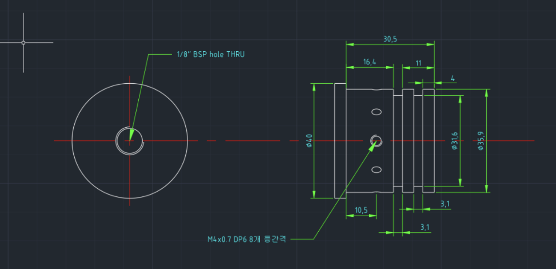
First, the rocket body was machined using aluminum-6061. The melting point of aluminum is lower than the combustion temperature, but because the grain is wrapped with paper, it takes time for the heat to transfer to the combustion chamber wall, and the combustion time is short, so it can survive without melting. In addition, the thickness of the rocket motor must be determined to withstand the pressure of the combustion chamber, and the thickness can be found using the formula below. 36 mm inner diameter with a safety factor of 3, combustion chamber pressure: 20 bar, and a stress of 80 MPa for aluminum 6061, we get a thickness of 2 mm.
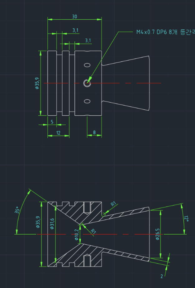
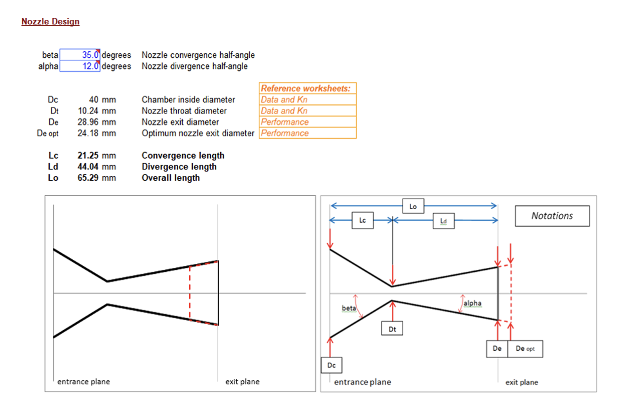
Second, the nozzle is optimized using SRM by Richard Nakka, and it looks like the picture below. Since the nozzle is the part where the hot flow rate passes through, we used SUS304, which has strong heat resistance and is resistant to combustion.
Third, the rocket's bulkhead is machined from aluminum.
Thrust Measuring Device
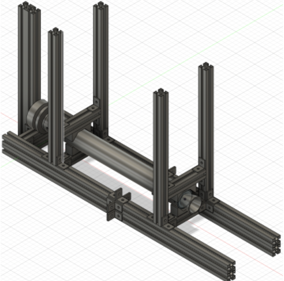
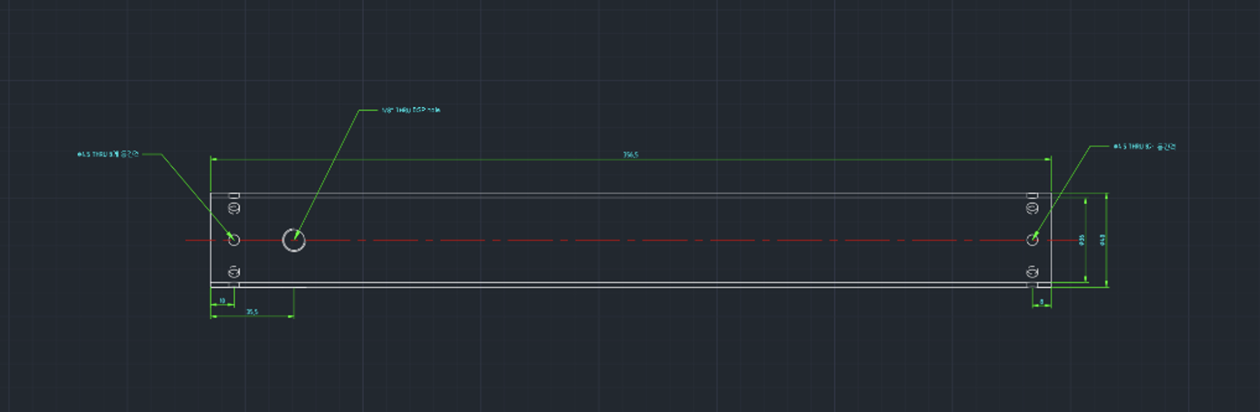
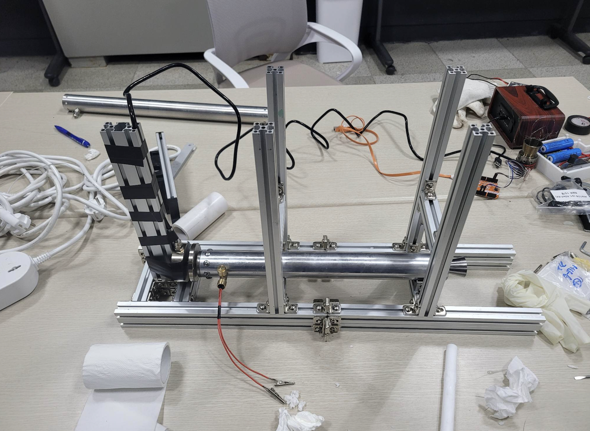
Once we've completed cooking the solid fuel, we'll need to experiment to measure its thrust data and graph of thrust over time. The total amount of work that rocket propellant can do to the rocket is determined by its ingredients and its mass, but the engine thrust's distribution over time and its burning time are highly dependent on the shape of the propellant core, which is the drilled-out part of the propellant. To collect such experimental data, we built a thrust measuring device. The main chassis of the device will be made of an aluminum profile (specifically, 2020 Aluminum profile) that is strong enough to withstand the thrust exerted by the rocket engine and will be shaped like a simple cube. In the center will be a fixture that prevents the rocket engine from escaping the device during the ignition tests, and there will be a load cell, the sensor that measures the exerted force. This sensor will be connected to a computer to obtain a graph of the thrust over time.
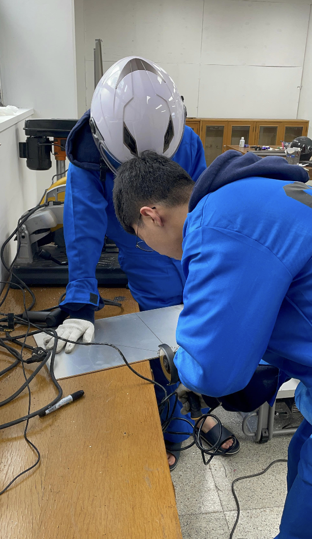
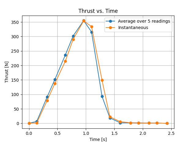
3rd Ignition Test Result
This was our first combustion experiment with an I-class motor with full 400g propellant. We were able to find out both problems and achievements. We realized that using a Metal Release Agent in the process of making the fuel effectively prevents the solid fuel from sticking. We also found that the ignition test results closely matched the expected thrust, so we knew that the test was carried out correctly. As for the improvements, first, BUZ has to make an engine with higher performance from the limited amount of solid fuel (According to South Korea’s law, a rocket containing solid propellant more than 400g is illegal). We conceived a new rocket fuel recipe, and it is expected to result in a performance increase of about 15%. Second, we need to measure the density of the fuel. If you don't measure the density of the fuel, you're going to get less than ideal performance because the viscosity and partial composition of the fuel you're currently processing may be different. Third, you need to use a pressure sensor. By measuring the combustion pressure, you can get the factors that determine the engine's performance, such as specific thrust and characteristic speed, so if something goes wrong, you'll know right away where the problem is. Fourth, in this experiment, we also found that the time interval between the load cell’s each thrust measurements was too long. For the more accurate data, we need data from tighter time interval. Currently, the time interval is 0.15 seconds. Our goal is to reduce the interval to 0.05 seconds or less by modifying the code.